How Far Apart Should Solar Street Light Poles Be?
Nov 13, 2026
Read:28
Source: Yin Zhenkun
Quick Answer: Solar street light poles are often spaced approximately 2.5–4 times their mounting height for preliminary planning, but there is no universal spacing requirement. The appropriate distance depends on road width, pole height, luminaire optics, lighting arrangement, and required illumination. For commercial and municipal road projects, the final spacing should be verified using photometric data and a lighting simulation rather than a general spacing chart.
A 30-meter pole spacing may provide suitable lighting on one road but leave noticeable dark areas on another. Even when two projects use the same mounting height and LED output, different beam distributions, road widths, and pole arrangements can produce significantly different lighting results.
For EPC contractors, lighting engineers, and project buyers, the more useful question is not simply how far apart the poles should be. It is whether a proposed or existing solar street light pole spacing can meet the required lighting performance without unnecessary equipment or installation costs.
This guide explains how to estimate spacing, assess different road layouts, evaluate existing pole positions, and use actual solar street light specifications when planning a project.
How Does Pole Height Affect Solar Street Light Spacing?
Pole height is one of the first factors considered when planning solar street light spacing. A higher mounting position can distribute light across a wider area, while a lower mounting position generally concentrates more light closer to the pole.
However, mounting height alone cannot determine the distance between poles. A luminaire with a suitable roadway distribution may provide more effective longitudinal coverage than another fixture with a similar lumen output but a narrower beam.
For preliminary planning, designers sometimes use a spacing-to-height ratio to estimate possible pole locations. The following table illustrates what an assumed ratio of 2.5–4 would produce.
| Mounting Height | Preliminary Spacing Range | Main Consideration |
|---|---|---|
| 4 m | 10–16 m | Pedestrian paths and smaller outdoor areas |
| 5 m | 12.5–20 m | Narrow access roads and walkways |
| 6 m | 15–24 m | Residential streets and local roads |
| 7 m | 17.5–28 m | Local roads with suitable optical coverage |
| 8 m | 20–32 m | Community roads and wider access roads |
| 10 m | 25–40 m | Wider roadways with appropriate optics |
| 12 m | 30–48 m | Main-road applications requiring detailed verification |
These figures are arithmetic examples based on an assumed 2.5–4 spacing-to-height ratio. They are not universal design limits or guaranteed performance recommendations.
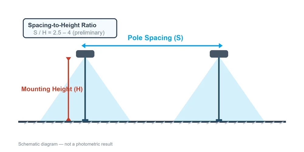
Road width also matters. A fixture mounted at 7 meters beside a narrow access road has a different lighting task from one installed at the same height beside a 20-meter-wide roadway. Increasing pole spacing without considering the full road width may leave insufficient light on the opposite side.
The luminaire's optical distribution is equally important. Roadway lighting commonly uses asymmetric or specialized optics to direct useful light both along and across the pavement.
The objective is not simply to maximize the illuminated area. It is to achieve the required lighting levels and uniformity while controlling glare and unwanted spill light.
The FHWA Lighting Handbook explains that roadway lighting design should consider pole geometry, luminaire photometrics, spacing, and placement together. Because optical distributions differ between products, suitable spacing can vary even when mounting heights are similar.
How Do You Calculate Street Light Pole Spacing?
A basic street light spacing calculation starts with the spacing-to-height ratio, usually written as S/H.
Spacing-to-Height Ratio = Pole Spacing (S) ÷ Mounting Height (H)
For example, consider a roadway with the following conditions:
- Mounting height: 12 m
- Existing pole spacing: 40 m
- Pole arrangement: Single-sided
- Lighting application: Main road
The calculation is:
S/H = 40 ÷ 12 = 3.33
This result falls within the commonly used preliminary range discussed above. However, it does not demonstrate that the road meets its required lighting classification.
A spacing ratio cannot determine whether the pavement receives sufficient light, whether illumination is reasonably uniform between poles, or whether the selected luminaire creates excessive glare.
A proper lighting calculation also considers the luminaire's actual optical distribution, road dimensions, mounting geometry, maintenance factors, and applicable lighting criteria.
Depending on the roadway classification and local requirements, the design may need to satisfy maintained illuminance, road-surface luminance, uniformity, and glare criteria.
For example, if a project specifies an M1 roadway lighting class, a 12-meter mounting height and 40-meter spacing cannot be approved simply because the S/H ratio appears reasonable. The lighting design must be evaluated against the applicable M1 requirements.
The initial formula is useful for early layouts and rough pole-count estimates. Photometric verification is needed to determine whether the proposed arrangement is technically suitable.
Which Pole Layout Works Best for Different Road Widths?
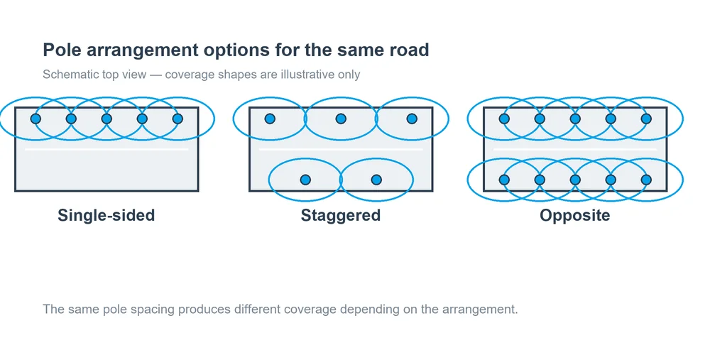
The same pole spacing can produce different lighting results depending on how the poles are arranged.
A road lighting layout generally uses single-sided, staggered, opposite, or median arrangements. The most suitable configuration depends on road width, lane arrangement, available installation positions, optical distribution, and required lighting performance.
| Pole Arrangement | Layout Description | Design Considerations |
|---|---|---|
| Single-sided | All luminaires are installed along one side of the road | Check whether light reaches the opposite side with adequate uniformity |
| Staggered | Poles alternate between both sides | Check longitudinal distribution and overlapping coverage |
| Opposite | Poles face one another on both sides | Evaluate overall coverage and longitudinal and transverse uniformity |
| Median | Poles are installed along a central reservation | Check road geometry, luminaire orientation, and suitability for divided roads |
For a relatively narrow local road, a single-sided arrangement may reduce the number of installation positions. On a wider road, however, the same arrangement could leave the opposite lane inadequately illuminated.
A staggered or opposite layout may improve flexibility when distributing light across the pavement, although additional poles and foundations can increase installation costs.
The final choice should be based on lighting calculations rather than assuming that one arrangement is always better.
Intersections, pedestrian crossings, bends, driveways, and other conflict areas require additional attention. Uniform spacing along a straight road does not automatically provide suitable lighting at junctions or crossings.
Pole placement may also be constrained by trees, overhead utilities, underground services, road access points, and roadside safety requirements.
For solar street lights, designers should also evaluate solar exposure. A pole location may be suitable for road illumination but receive insufficient sunlight because of nearby buildings or vegetation.
Where shading cannot be avoided, the designer may need to consider a revised pole position or a different solar panel arrangement.
Can Existing 25m, 40m or 100m Pole Spacing Be Used?
Not every solar street lighting project begins with a new road layout.
Many projects involve existing poles, fixed foundations, or road sections where installing additional poles would be expensive or difficult.
In these situations, engineers should first determine whether the available pole positions can support the required lighting performance before selecting the luminaire.
The following examples illustrate how the evaluation changes with different spacing and road conditions.
| Existing Pole Spacing | Road Conditions | Key Engineering Questions | Possible Design Direction |
|---|---|---|---|
| 25 m | Wide road, approximately 20–25 m | Can the optical distribution and pole arrangement cover the complete roadway? | Compare single-sided and two-sided layouts through photometric calculations |
| 40 m | Existing 12 m poles with M1 lighting requirements | Can the selected luminaire meet the required luminance, uniformity, and glare criteria? | Evaluate model-specific photometrics and alternative optical configurations |
| 100 m | Existing roadway with widely separated poles | Will excessive spacing produce unacceptable dark areas? | Assess additional lighting points, revised arrangements, or another lighting solution |
These scenarios illustrate engineering design considerations rather than completed photometric calculations.
For 25m spacing, the primary challenge may be road width rather than longitudinal distance. A roadway approximately 20–25 meters wide could require different optical distributions or two-sided lighting, depending on its classification and performance requirements.
A manufacturer's published 25m spacing reference does not automatically establish suitability for every 25m road layout.
For 40m spacing, retaining existing 12m poles may be possible, but the chosen luminaire must still meet the relevant lighting criteria. A higher-output fixture may increase average brightness without sufficiently improving the darkest areas between poles.
For 100m spacing, the design requires more substantial evaluation. Such a distance exceeds the published reference spacing of many conventional solar street light products. Increasing wattage alone is unlikely to demonstrate adequate coverage without examining alternative layouts or additional lighting positions.
What If Existing Pole Positions Cannot Be Changed?
Fixed pole positions do not automatically mean that a project cannot proceed. They do, however, limit the design variables available to the engineer.
Possible approaches include selecting a different optical distribution, reviewing mounting-arm geometry, adjusting luminaire orientation within approved limits, or introducing additional lighting points where necessary.
For solar conversion projects, the existing poles also require structural assessment.
A solar panel, battery enclosure, mounting bracket, or integrated solar luminaire may introduce additional weight and wind loading. The pole's capacity, foundation, and mounting interface must be reviewed before installation.
A pole that can support a conventional LED street light is not automatically suitable for every solar street lighting configuration.
Project cost should also be considered alongside lighting performance.
| Design Option | Potential Benefit | Main Limitation |
|---|---|---|
| Increase pole spacing | Fewer poles and foundations | Greater risk of insufficient uniformity |
| Use higher-output luminaires | More available light output | Higher output does not necessarily correct poor distribution |
| Select alternative optics | Better alignment of light with road geometry | Requires suitable photometric data and verification |
| Add lighting points | More flexible coverage and positioning | Higher equipment and installation costs |
| Reuse existing poles | Potential reduction in civil work | Structural, mounting, and solar-exposure constraints |
A reliable solution balances illumination quality, energy demand, installation cost, and long-term maintenance.
For practical installation considerations, see RoadSmart's Solar Street Light Installation Guide.
How Do IES Files and DIALux Verify Pole Spacing?
A spacing chart provides an initial estimate. An IES photometric file provides more detailed information about how a specific luminaire distributes light.
The file describes the luminaire's luminous intensity at different angles. Lighting design software such as DIALux can combine this information with actual road geometry and pole positions to model the expected lighting performance.
A typical evaluation includes five stages:
- Define the road dimensions, classification, lane arrangement, and lighting requirements.
- Enter the proposed mounting height, pole positions, mounting-arm geometry, and luminaire orientation.
- Import the photometric file corresponding to the exact luminaire configuration being evaluated.
- Calculate the relevant lighting metrics, including maintained illuminance or luminance, uniformity, and glare where applicable.
- Adjust the fixture selection, optical distribution, arrangement, or spacing until the design meets the required criteria.
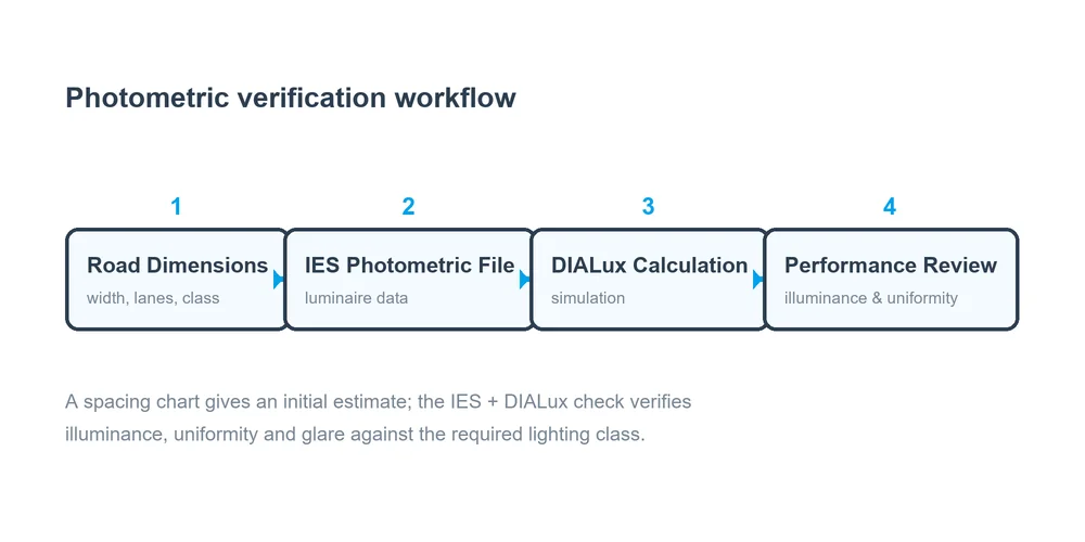
The Caltrans Roadway Lighting Guidance describes the use of roadway geometry and manufacturer IES files in lighting calculations and the importance of field verification.
For project buyers, this means a product's advertised wattage, lumen output, or recommended spacing should not replace project-specific photometric calculations.
A model with greater luminous flux does not necessarily produce better uniformity. Optical distribution and mounting geometry determine where the available light reaches the pavement.
Does Nighttime Dimming Affect Road Lighting Performance?
Solar street lights introduce another consideration: actual light output may change during the night.
Unlike a grid-powered fixture operating continuously at one output level, a solar street light may use programmed dimming or sensor-based control to manage battery energy consumption.
For example, the RoadSmart HS Series technical datasheet documents several operating modes, including one schedule with 100% output for two hours, 70% for two hours, and 30% until dawn.
A road that meets its lighting requirements at full power may not necessarily meet them during a reduced-output period.
If all luminaires dim by the same percentage while maintaining their optical distribution, relative uniformity can remain similar even as overall illuminance or luminance decreases.
If individual fixtures operate at different output levels, the spatial distribution of light may also change.
Therefore, lighting verification should consider the required operating schedule, not only the fixture's maximum rated output.
Solar panel capacity, battery storage, local solar resources, and backup autonomy should also be evaluated to determine whether the proposed lighting schedule is sustainable.
These factors are especially important for off-grid roads and locations with limited electrical infrastructure.
How Does RoadSmart Apply Pole Spacing in Real Projects?
RoadSmart provides solar street lighting solutions for different mounting heights, road layouts, and project requirements.
Its published specifications offer useful preliminary spacing references, while product selection should also consider actual site conditions and lighting requirements.
The HS Series technical datasheet and a Solar Star Light installation in Nigeria illustrate how manufacturer specifications and real installation conditions can support project planning.
RoadSmart HS Series: Manufacturer-Published Spacing Reference
The RoadSmart HS Series specification document provides the following technical data:
| Specification | RS-HS300 | RS-HS400 |
|---|---|---|
| LED Power | 100 W | 130 W |
| Luminous Flux | 16,000 lm | 20,800 lm |
| Recommended Mounting Height | 8–12 m | 10–12 m |
| Recommended Spacing | 25–35 m | 25–35 m |
| Beam Angle | 60° × 140° | 60° × 140° |
| IP Rating | IP65 | IP65 |
Source: RoadSmart Solar Street Light HS Specifications, 2025 V1.1.
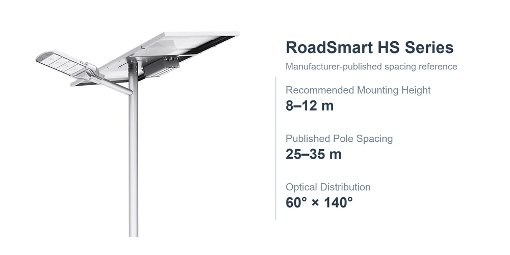
The published 25–35m spacing range can help engineers and project buyers prepare an initial road lighting layout.
However, it should not be treated as a guaranteed spacing for every road width, pole arrangement, or lighting classification.
Where a project specifies a particular roadway lighting class, the selected luminaire configuration should be evaluated using the relevant photometric data and road geometry.
Other RoadSmart product series, including the RSG-Pro Series and RSE Series, provide additional configurations for different mounting heights and project requirements.
Project Example: Solar Star Light Installation in Nigeria
A RoadSmart Solar Star Light installation in Nigeria illustrates how pole spacing is applied under actual site conditions.
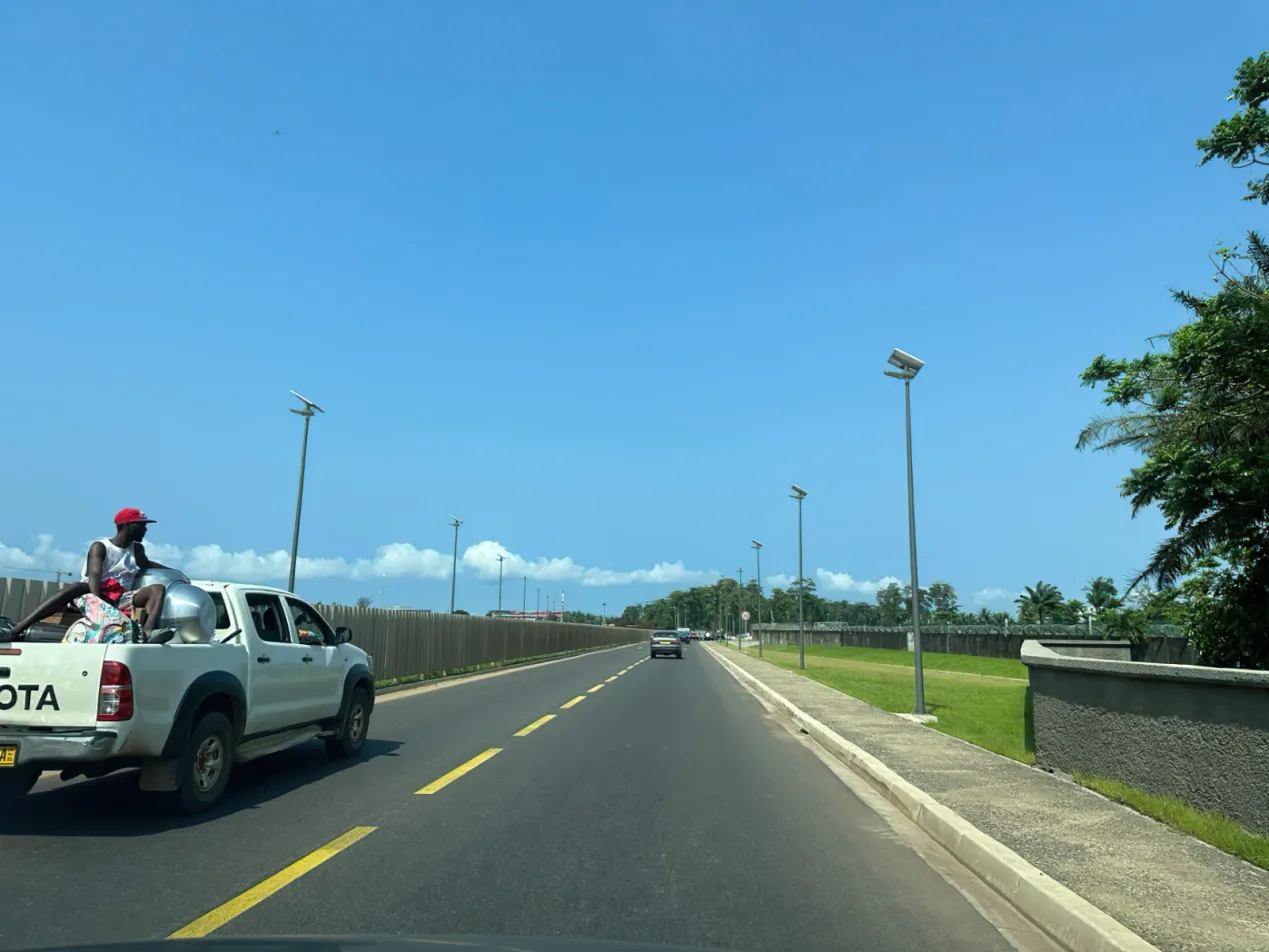
The available project records identify a 7m mounting height and 30m pole spacing. The installation photographs show the roadway, pole positions, and nighttime lighting appearance.
The project identifies the Solar Star Light ST2 series. For current product selection, the standard ST2-60 specifications published on RoadSmart's official website are shown below.
| Parameter | Current Standard ST2-60 Specification |
|---|---|
| Product Series | Solar Star Light II |
| Model | ST2-60 |
| Solar Panel | 60W / 18V |
| Battery | 240Wh LiFePO4 |
| Luminous Flux | 6,000 lm |
| Color Temperature | 3000–7500K |
| Light Distribution | Batwing lens with polarized light |
| Recommended Mounting Height | 6–7 m |
| Published Installation Spacing | 20–40 m |
Source: RoadSmart Solar Star Light II — Official Product Specifications.
These are the currently published standard-model specifications. They are provided as a product reference and do not independently confirm every component fitted to the photographed installation.
The documented Nigerian installation uses a mounting height of 7m and pole spacing of 30m, giving a spacing-to-height ratio of:
S/H = 30 ÷ 7 = 4.29
This value is slightly above the commonly used preliminary ratio of 2.5–4 discussed earlier.
It illustrates why preliminary height multipliers should not be interpreted as universal maximum spacing limits.
Road geometry, optical distribution, and lighting requirements must be considered when assessing whether a particular spacing is suitable.
The current ST2-60 product specifications list a recommended mounting height of 6–7m and a published installation spacing reference of 20–40m for the ST2 range. However, the final suitability of 30m spacing still depends on the actual road and required lighting performance.
Daytime project photographs help illustrate the installed pole arrangement and road environment. Nighttime photographs provide a visual reference of the installation under operating conditions.
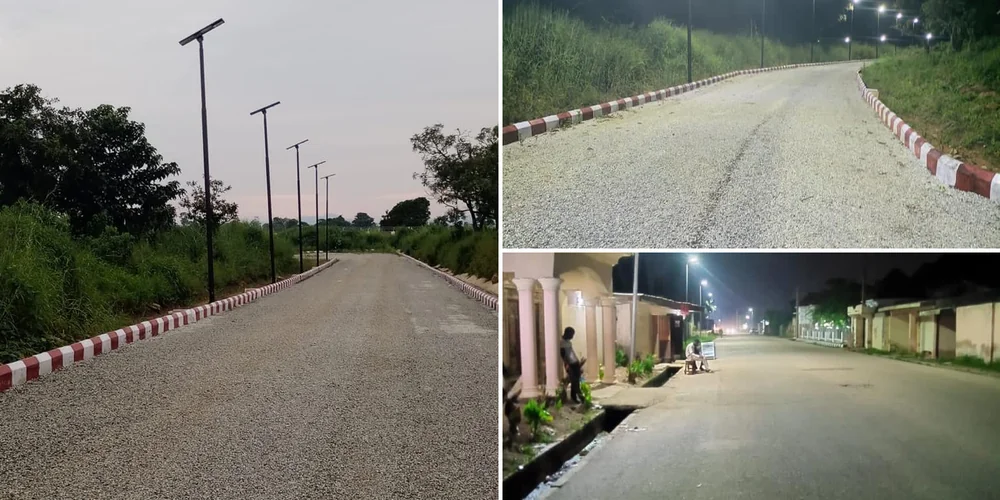
Solar Star Light Installation in Nigeria — 7m Mounting Height, 30m Pole Spacing
Photographs alone, however, cannot confirm compliance with a specified illuminance, luminance, or uniformity requirement. Such conclusions require appropriate photometric calculations and, where specified, field measurements.
The Nigerian installation is therefore a useful real-world reference for understanding mounting height and spacing, rather than a universal recommendation for every road using 7m poles.
For current model options and technical parameters, visit the Solar Star Light II product page.
What Information Should EPC Contractors Provide for a Spacing Review?
For a new road project or an existing pole retrofit, a reliable lighting recommendation starts with accurate site information.
A supplier cannot determine a suitable luminaire simply from the requested wattage or the distance between two poles. Road geometry, operating conditions, and technical requirements are equally important.
The following information supports an initial engineering review:
| Required Information | Why It Matters |
|---|---|
| Project location | Determines local solar resources and environmental conditions |
| Road width and number of lanes | Defines the area requiring illumination |
| Road classification and lighting requirements | Establishes target lighting performance |
| Existing or proposed mounting height | Influences coverage and mounting geometry |
| Pole spacing and arrangement | Determines fixture positions and longitudinal coverage |
| Existing pole dimensions and structure | Supports mounting and structural compatibility assessment |
| Operating hours and dimming schedule | Defines nighttime lighting and electrical demand |
| Backup autonomy requirement | Supports solar panel and battery sizing |
| Road drawings or site photographs | Helps identify obstacles and installation constraints |
| Project quantity and procurement requirements | Supports product configuration and commercial planning |
For existing-pole projects, technical drawings and site photographs are especially useful. They can reveal installation restrictions that are not apparent from spacing figures alone.
For wider roads, specified lighting classifications, or complex arrangements, the review should also consider relevant photometric documentation and lighting calculations.
Planning a Solar Street Lighting Project?
Whether your project involves 25m spacing, existing 40m pole intervals, or a road requiring a new lighting layout, RoadSmart can review your project information and discuss suitable solar street light configurations.
Share your road width, mounting height, pole spacing, lighting requirements, operating schedule, and project location to request product specifications and discuss available photometric documentation.
Frequently Asked Questions About Solar Street Light Spacing
1. Can I replace existing street lights with solar lights without changing the poles?
Yes, existing poles may be reusable if their structural capacity, mounting dimensions, solar exposure, and lighting layout are suitable for the selected solar street light. Engineers should verify additional wind loading, fixture weight, mounting compatibility, and photometric performance before approving the retrofit. Reusing existing poles does not automatically mean their current spacing will provide adequate road illumination.
2. Can 40m pole spacing work for a solar street lighting project?
A 40m spacing may be feasible under some road conditions, mounting heights, and optical distributions. However, spacing alone is insufficient to confirm suitability. For example, a road with 12m poles and M1 lighting requirements must be evaluated against the applicable luminance, uniformity, and glare criteria. A photometric calculation is needed before confirming the layout.
3. Will higher-wattage solar street lights eliminate dark spots?
Not necessarily. Higher wattage may increase available light output, but dark spots can result from unsuitable optical distribution, excessive spacing, or mounting geometry. A different beam distribution or additional lighting point may be more effective than increasing wattage alone. Higher electrical demand also affects solar panel and battery sizing.
4. How many solar street light poles are needed for a 1km road?
For a preliminary estimate, divide the road length by the proposed spacing. At 30m spacing, a 1,000m road contains approximately 33.3 spacing intervals. Depending on how the endpoints are treated, a single-sided arrangement may require approximately 34–35 poles. Staggered or opposite arrangements require separate calculations. The final quantity depends on road geometry, junctions, pole arrangement, and lighting requirements.
5. Does nighttime dimming affect solar street light spacing design?
Yes. Even when pole locations remain unchanged, dimming reduces the available light output. Uniform dimming may maintain similar relative uniformity while reducing average illuminance or luminance. Sensor-based or independently controlled fixtures can produce different lighting patterns. Projects with specified lighting performance requirements should verify the relevant operating states rather than relying only on full-power calculations.
References
Federal Highway Administration (FHWA). FHWA Lighting Handbook. Roadway lighting design, pole arrangements, photometric characteristics, and lighting calculations.
Federal Highway Administration (FHWA). Roadway Lighting Details. Roadway lighting layouts, optical distribution, and site design considerations.
California Department of Transportation (Caltrans). Roadway Lighting — Traffic Operations Manual, Chapter 205. Photometric documentation, lighting analysis, and field verification.
RoadSmart. Solar Street Light HS Specifications, 2025 V1.1. Manufacturer-published mounting height, spacing, luminaire specifications, and operating modes.
RoadSmart. Solar Star Light II — Official Product Specifications. Current ST2 model parameters and installation references.
Table of Contents